Insights: Understanding Variable Frequency Drives and Harmonic Mitigation
The pursuit of energy efficiency and reduction has become a popular topic of conversation surrounding the A/E/C industry in recent years, and it is not something that will be going away anytime soon. Despite the situation we all find ourselves in with regards to the pandemic, we will continuously try to build a more energy efficient environment for future generations.
Variable Frequency Drives (VFD’s) are becoming increasingly more prevalent as an efficient solution in order to control the extensive amount of energy used by motors in facilities around the world. VFD’s control motors by varying the voltage and frequency that is being used by the motor’s windings. As the voltage and frequency continue to build, the motor’s windings become magnetized and operate the motor.
Many motors still contain basic starters, which start motors “across the line”. This means upon start-up there is a subsequent demand for 300-600 times the motor full-load current. The main disadvantage to this starter type is the inability to vary a motor’s speed control, causing the motor to run at (or close to) synchronous speed for the majority of its useful life. The inability to control these motors results in increased demand, causing higher costs in energy usage for consumers. VFD’s become attractive to facility owners due to their speed control capability directly resulting in a significant reduction in utility costs and a longer lifetime for the motor.

There is no debating VFD’s provide an efficient way to start and control electrical motors, however, they do provide some challenges to electrical distribution systems in the way of harmonics.
Every electrical system will experience a certain amount of harmonic contribution; however, with the increased use of electronic equipment, harmonic levels have the potential to increase. Mitigating these harmonics to prevent damage to electrical systems is critical. Engineers, designers, and scientists have been combatting harmonics for years; however, this battle has escalated in recent years due to the in-flux of non-linear loads, namely VFD’s. Harmonics are generated through non-linear loads by drawing current and creating abrupt pulses that distribute themselves back into electrical systems. Facility electrical systems will remain resilient to these harmonic currents until the harmonic contribution begins to approach levels that begin to alter how the system can sense and respond to these increased currents. Harmonic contribution can become a leading factor in the following occurrences:
- Nuisance tripping of circuit breakers and fuses resulting in increased maintenance costs and facility downtime.
- Harmonic resonance resulting in poor power factor (PF) and increased utility costs.
- Equipment overheating and possible fire resulting in damage to the facility and equipment.
- Neutral overloading resulting in damage to conduit and wiring potentially leading to fires.
- Electro-magnetic interference to sensitive equipment resulting in loss of communication and/or monitoring of the equipment.
- Motor winding burnout causing damage to expensive motors that are typically the backbone to critical facilities.
As can be seen in the list above, harmonics are a serious matter and cause significant issues for various types of facilities that rely heavily on the usage of electricity. Therefore, harmonic mitigation is typically required for facilities that contain a minimum of 20-25% non-linear loads.
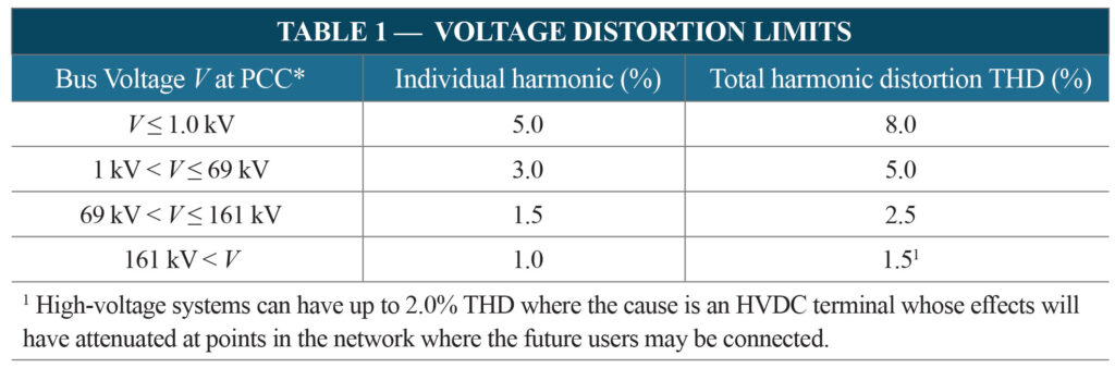
The governing body that is responsible for overseeing and providing standards for VFD’s is the Institute of Electrical and Electronics Engineers (IEEE). The specific standard responsible for setting the guidelines around harmonic contribution is IEEE Standard 519, Recommended Practices and Requirements for Harmonic Control in Electrical Power Systems. Table 1 from IEEE 519-2014 is displayed below and can be used as a guideline for the total harmonic distortion (THD) limits in relation to voltage at certain points in the system.
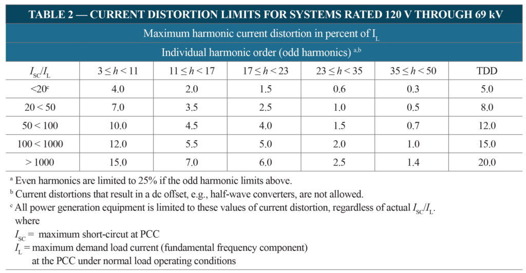
Additionally, IEEE-519 Table 2 provides the current distortion limits for systems 120V to 69kV.
A common misunderstanding for engineers and designers is the idea that these percentages must be maintained at the piece of equipment they are installing. Many times engineers and designers will simply confirm with the VFD manufacturer that their particular piece of equipment is IEEE 519 compliant without looking at the system as a whole. As you can see from the table above, the bus voltage is referenced at the Point of Common Coupling (PCC). The PCC is described as, “The point on a public power supply system, electrically nearest to a particular load, at which other loads are, or could be, connected. The PCC is a point located upstream of the considered installation.” More often than not, the PCC is located at the main switchgear near the utility tie-in. As mentioned above, utility providers remain diligent in monitoring the power factor of their system. A facility with significant harmonic contribution may be subject to fines from the utility, or required to purchase and install costly PF correction equipment at the facility.

Senior Project Engineer
The first step in identifying a harmonics problem is applying a meter to measure the total harmonic distortion (voltage and current), including individual harmonic order distortion levels (H2-H35) within the distribution system. If these meters are not installed internal to the piece of equipment, an electrician has the ability to measure these harmonics. C&S has regularly deployed an in-house electrician and meter responsible for the monitoring and recording of harmonic levels. Once the data has been gathered, the next step is to use sophisticated system modeling software to analyze and simulate harmonic mitigating techniques such as; active/passive filters, harmonic mitigating transformers and VFD line reactors. This approach is the most efficient way of determining if VFD installations will result in having negative effects on the electrical system. With the capability to run harmonic studies using in-house software’s, C&S can ensure a facility is operating efficiently and effectively without the introduction of harmful harmonics!
References: (1) Square-D Company, IEEE Standard 519
If you have questions, or would like to learn more, please feel free to reach out to Rob at (585) 713-1891 or rgleason@cscos.com.